"International friendship through amateur radio"

Category: Equipment

MMSSTV and the IC705

A recent SOTA gauntlet challenge set by Tom M1EYP spurred me into trying something old but new. Years ago, back in the dark ages of Windows XP I had a dabble in HF SSTV using the then popular MMSSTV program.

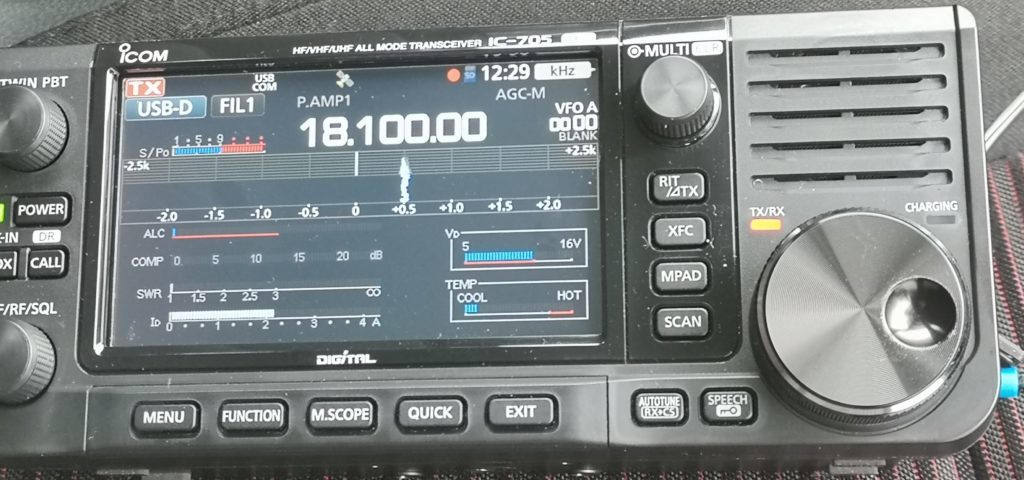
This is still available to download, but has not been updated since 2011, and officially does not support Windows 10, or the modern radios for pseudo-cat interfacing. As my weapon of choice these days is the Icom IC705, a quick google search returned a useful web page from M0IAX, who in turn had published the information from the web site of VK3DAN.

I am indebted to both for the the information, but can add a couple of gotchas, and hopefully help other 705 users avoid a long walk up a mountain only to find it doesn’t work – ask me how I know.

Download and install MMSSTV – there are several places on the interweb, the latest version is 1.13, thats the one you want.

The software .ini fie will need modification to make it compatible with the 705.

Using fie explorer, navigate to C:\Ham\MMSSTV if you used the default settings. Locate mmsstv.ini

Open mmsstv.ini in notepad – Find the two sections shown below in the original fie, then cut and paste the following content:

[RADIO]
PortName=COM3
BaudRate=9600
BitLen=1
Stop=1
Parity=0
flwXON=0
flwCTS=0
usePTT=0
ByteWait=0
Cmdxx=164
CmdInit=
CmdRx=\$FEFExxE01C0000FD\
CmdTx=\$FEFExxE01C0001FD\
FileGNR=
OpenGNR=0
PollType=3
PollInterval=5

[RadioMenu]
Menus=10
Cap1=3.640 MHz LSB – Aus. Call
Cmd1=\$FEFExxE00500006403FD\$FEFExxE02600000101FD
Cap2=7.043 MHz LSB – Intl Call
Cmd2=\$FEFExxE00500300407FD\$FEFExxE02600000101FD
Cap3=7.170 MHz LSB – Australia, USA Call
Cmd3=\$FEFExxE00500001707FD\$FEFExxE02600000101FD
Cap4=10.132 MHz USB – Call USB
Cmd4=\$FEFExxE00500201310FD\$FEFExxE02600010101FD
Cap5=14.230 MHz USB – Intl Call
Cmd5=\$FEFExxE00500002314FD\$FEFExxE02600010101FD
Cap6=14.233 MHz USB – Digital Call USB
Cmd6=\$FEFExxE00500302314FD\$FEFExxE02600010101FD
Cap7=14.240 MHz USB – Euro Call
Cmd7=\$FEFExxE00500002414FD\$FEFExxE02600010101FD
Cap8=21.340 MHz USB – Intl Call
Cmd8=\$FEFExxE00500003421FD\$FEFExxE02600010101FD
Cap9=28.680 MHz USB – Intl Call
Cmd9=\$FEFExxE00500006828FD\$FEFExxE02600010101FD
Cap10=50.950 MHz USB – Intl Call
Cmd10=\$FEFExxE00500009550FD\$FEFExxE02600010101FD

In the ini fie, locate

[RADIO]
PortName=COM3

Change the port number to the one you use for your system – you can find this in “device manager – com ports” if you are not sure which port to use.

Save the new ini fie, and you should be good to go.

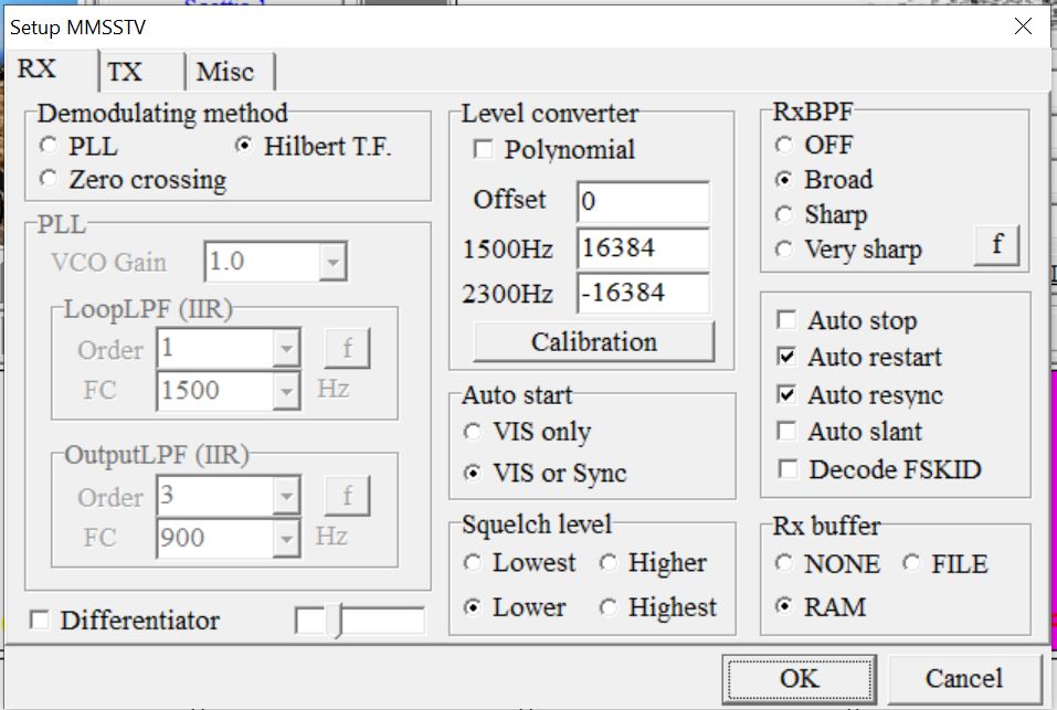
I found to my cost that the settings sometimes glitch on a Win 10 machine. If you loose coms to the radio, check the options in mmsstv – option>>setup mmsstv

The RX option screen should look like this:

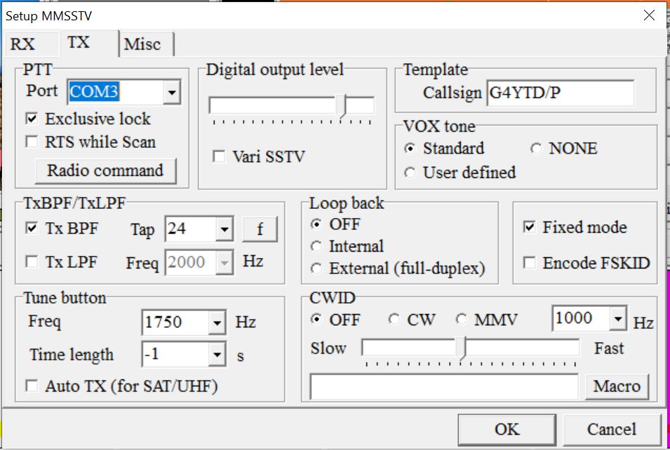
The TX option screen should look like this (with PTT Port set to your com port – mine is Com3):

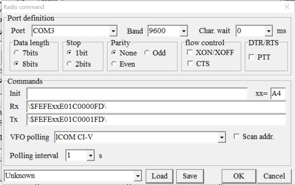
Click the “Radio command” button on the TX option screen and confirm that the correct com port is selected, if not, change it on the drop down, check that the VFO Polling is set to ICOM-CI-V and click ok.

The Radio command screen should look like this:

That should be it – mmsstv now working.

Have fun

73

Tim

G4YTD

QCX 30m Bamotech case and calibration

QCX 30m in Bamotech custom case

Another step nearer to using the latest addition in anger.

The PCB is now living in the custom built Bamotech case, is calibrated and optimised to give higher power output than the the original 0.7w.

Calibration is easy, follow the instructions to optimise the rx and tx.

If you have the Qrp Labs GPS unit, make a 4 way lead to connect the GPS to the QRX PCB. This is not clear in the instructions.

The GPS is powered from the 4 way connector on the QCX pcb – no external power needed for the GPS – make sure your pin to pin connections are correct by referring to the manuals and schematics for both units.

By selecting the correct menu function, the GPS will set the frequency offsets etc in less than 30 seconds and you are ready for the tx optimisation.

PCB in the custom case

Hans produced a comprehensive video showing the procedure for optimising the BPF and how to increase the TX power.

Video here

Following the guidance on the video, 2 turns were taken off the torroid and the others either pinched or expanded as described. Power output increased from 0.7w to 3.8w at 12v.

At 13v the power was just over 5w.

Text book tuning!

The last thing on the list is to source a 5.5mm/2.1mm power connector to marry up with the Bamotech supplied power socket – frustrating that they dont supply the power plug with the case kit.

RS components in the UK have the plugs, but with £4.95 postage on an 88p plug, it is a bit steep.

3.5w at 12v

Very happy with this radio, a lot of thought has gone into the design and the user manuals, and using a home built radio is very satisfying.

73

Tim

50A Power supply for peanuts

Following the successful repair of the MML144-200 2m Amp, and needing a high current stabilised power supply to feed it, I cannot thank Len, GM0ONX enough for putting me on to this server power supply.

Designed to run 24/7/365 for 7 years without maintenance, and provide up to 63A continuous current output at 12v, you would think that you couldn’t afford one – especially as it says HP on the rating plate.

Think again.

These power supplies are switch mode units, and as such are generally avoided like the plague for radio use. However, this model for me at least is RF quiet on the bands I operate.

The best part is I purchased two guaranteed working used units from eBay (12th Feb 2021) for £15 delivered – that was for both of them! £7.50 each. Significantly cheaper than a new desktop PSU from one of the radio suppliers.

HP server PSU

Very important: – Make sure the model number is this:

HP ProLiant DL360 G6 750W Power Supply (HSTNS-PD18 version)

Google or Youtube will provide loads of information on modifying server power units.

This post only applies to the model shown above.

There are a couple of very simple mods to do to them before you can use them.

  1. Power on mod
  2. Variable voltage mod

As these are designed to be installed in a server you will need to bypass the server start up and monitoring system.

On the edge connector solder a jumper between the first pin and the ground tab (shown by the yellow wire)- you can also add a switch if you want to, or as soon as power is applied the device will turn on.

Next add a 22k resistor as shown below (between pins 4th from the left and 5th from the left)

Jumper first pin to Ground (-Ve) and a 22k resistor between 4 + 5 as shown

Connecting power will start the power supply, you should see 12v on the edge connector (polarity as shown with the black and red croc clip)

The next job is to mod the regulator to allow adjustment to 13+ Volts.

Add a 22k resistor between the left leg of the potentiometer, and the fourth pin from the right on the vertical board as shown below.

22k Resistor, heatshrink protected from 4th pin to left leg of pot

Connect the power and adjust the pot to the desired output, in my case 13.6v.

On my examples, at 13.8v the protection circuits can kick in and shut things down on switch on. When backed off to 13.6v the system was happy.

Place the insulating shield back into position, screw down the covers and you are good to go.

Both units worked first time, I now have a capacity of 100A plus if needed for less than £20.

A case, meters, fuse holders, and power pole chassis sockets are on order ready to box up the units, more on this shortly.

73

Tim

Microwave modules MML-144-200

This was one of those impulse purchases, you know the ones, you lusted after something when you were first licensed (15 years old in my case), but couldn’t quite justify the expense? Well due to sad circumstances one of these extremely rare blasts from the past appeared on the club web site, one of our club members had sent his last transmission and was now SK. Long story short, sealed bid auction, I won it and became the proud owner of this heavy and rather nice looking 80’s 2m amp.

There are many 30w and 100w versions in circulation, but the 200w amp is a rare beast indeed. Anyway, after hooking it up to the shack psu and turning it on, all the lights went out, not just the amp, the entire house!

Not a well amp.

Information on this version – V1 as far as I can find out, is scarce, it is a 25w input, 200w out solid state PA for 2m, current draw is going to be 40A plus I would guess. Internet searches turned up a circuit diagram of sorts and provided a place to start.

This image has an empty alt attribute; its file name is IMG_20201127_150932-768x1024.jpg
Feet in the air and bottom cover off – Sick MML200

Starting at the power leads (which were in pretty poor condition), the multi meter confirmed dead short across the leads. The circuit diagram was showing an idiot diode across the input, and as the PCB is old school, it took no finding. The multi meter again confirmed that the reverse polarity diode appeared to be short circuit. To be sure, one leg was lifted, and the diode checked again, both polarities. It was toast, short in both directions.

This image has an empty alt attribute; its file name is IMG_20210202_153437-768x1024.jpg
Reverse polarity diode – one leg lifted for checking

Luckily the junk box had a spare 1N4007, the offending article was replaced, and an ohm meter test now displayed several Meg-ohms across the input.

Power was applied again, and with the current throttle set to 3A the beast was switched on. The relays fired and the amp burst into life. Setting the mode to FM, connecting a dummy load and power meter, and giving the input a squirt of RF from an FT70, the meter deflected over to 10w, an expected output for 1w input. Increasing the drive to 5w gave 50w. The FT70 was swapped for a wouxun 2m giving 7w out, the amp gave a solid 70w.

This image has an empty alt attribute; its file name is IMG_20210205_144606-1024x768.jpg
70w out for 7w in

The power supply was starting to complain at this level due to current draw, but in all, I am feeling pretty confident that the amp will get close to the 200w with enough drive and current availability. Next tests will be spectral purity with the spectrum analyser, and then on the air to see what it is capable of once the big psu (60A) is retrieved from storage.

In summing up, I always wanted one of these back in the mid 80s, and for the price paid for it from the SK sale, very pleased that the repair cost less than 12p and 30 minutes to sort out.

Beam North and see if you can hear me on 2m SSB

73

Tim

G4YTD

QRP Labs QCX 30m kit

Whist the current lack of travel is frustrating, and the enforced “house arrest” isn’t helping much, it has given the opportunity to make progress on some of those projects that have been gathering dust for a while.

Some time ago a QCX 30m kit arrived in the post from Hans Summers of QRP labs. The kit is well packaged and contains everything you need to get on the air. I must congratulate Hans on the quality of the build notes, all 150 pages of them. This is not as daunting as it sounds, as experienced builders can skip a lot of the information, and new builders can take in the many tips and step by step instructions.

The radio is a single band 5w QRP CW only radio that has a whole host of features built in including CW keyer, CW decoder, test equipment, LCD display and ability to link to a GPS time source for WSPR transmissions and frequency calibration.

It took me a couple of nights to build, and the excellent instructions saved any problems when winding the torroids.

This image has an empty alt attribute; its file name is IMG_20210127_160026-768x1024.jpg
QCX PCB Completed

Once built, and checked for short circuits, power was applied, so far so good, no smoke! The next job is to set up the LCD, turning the brightness pot up a little illuminated the display with a prompt asking the builder to choose the band – in my case 30m (Band choice is chosen by the BPF that you build and fit to the PCB). The next step is to set up the receiver, again step by step using the built in test equipment and covered in great detail in the build notes.

This image has an empty alt attribute; its file name is IMG_20210127_170014-1024x768.jpg

At last it was time to test the TX, with a watt meter and dummy load attached, the transmitter can be tested by pressing the in built microswitch (that also acts as a straight key) the power meter kicked over to 0.8w output, not bad for a first transmission, at least there was no smoke. Using the inbuilt “key” for a quick CQ G4YTD instantly decoded on the screen. This feature can be turned off, but is a good aid for new CW operators.

This image has an empty alt attribute; its file name is IMG_20210127_172345-1024x768.jpg
First TX

Frequency offset against display was a little off when measured on a frequency counter. Hans has this covered by use of a GPS driven signal source. The QCX can take data from several GPS units, but QRP labs also offer a low cost kit to build one. I purchased one with the QCX, the build took around 1 hour to complete. At the time of writing I am waiting for a 4 way molex connector to arrive in the mail, and will then use the GPS to calibrate the QCX further.

This image has an empty alt attribute; its file name is GPS-1024x717.jpg
QRP abs GPS card

The satisfaction of listening to 30m on a home built radio took me back to when I was first licensed in 1984 using a home brew HF rig, who needs the latest gazillion £ Yaewoodcom radio to have fun?

Next steps on this project are to tweak the torroids to up the power a bit closer to 5w, and finish calibrating before boxing up in the Bamotech enclosure and giving it an airing.

73

Tim

G4YTD

Living with the Icom IC705

Having had a month of lockdown with the 705, here are a few observations and additions I would like to share.

This radio was obtained to use when weight was not an issue, that is to say, portable operations that do not involve climbing mountains and very long walks (SOTA) where weight is a big issue.

The radio is a joy to use, either as the main base radio, or low impact portable rig to be used either barefoot, or with some kind of amplifier.

Whilst the World craziness continues, beach use with the kite has not happened and will be the subject of another article, pity as the home beverage has picked up VK and ZL on 80m on many early morning monitoring sessions.

So, where do we start?

The biggest niggle with the 705 is the inherent instability, and the fact it falls over easier than a drunk on a Saturday night. Searching the forums and user groups, this is the main cause of dissatisfaction with the radio.

Luckily the answer is quite easy to implement, many people, myself included are using a tripod to camera adaptor, there are many around ranging from dirt cheap to eye watering expensive. I opted for a heavy weight anodised aluminium tilting mount from Neewer. The mount was on promo on Amazon (UK) and cost less than £20 delivered. This mount has a thumb screw integrated into the housing and is very easy to fit and remove from the radio. As it is quite heavy, I wouldn’t want to carry it on a SOTA activation, but it keeps the radio upright and stable when used in a vehicle or on a table. As a side note, on the base of the mount, there are small integrated rubber feet that stop the radio sliding if used on a smooth surface.

Neewer photo mount closed
Neewer Photo mount open
IC705 on Neewer tripod mount

The second point is Icom only (currently) sell one carry case for the radio – the super expensive sell a kidney to buy one backpack. Whilst this is the ultimate bling carry pack, for my own use, serves no purpose. It is a great idea, but lacks many of the functions of a hiking or climbing rucksack, and does not offer me enough space for the safety and foul weather kit I choose to carry. I can see the Icom bags use in short strolls, or operating from a park or beach, but I needed something that was lightweight, would fit in an existing backpack, could be used from a car or camper van, and wouldnt take much space at home when not in use. One of the other hobbies here is photography, and having several camera and lens holders from Lowepro, this was the obvious choice for my needs.

The bag had to have enough space for the battery, mic, power and data leads, everything else I would need would be carried in ex military pods and packs, or in the tote box that has wheels and doubles up as a table when on a beach or at the side of the car.

By coincidence, the Lowepro Edit 140 is exactly the right size for the job, costing about £30 in the UK at the time of writing (January 2021) it is significantly cheaper than the Icom backpack, and will fit into any of the walking rucksacks I have, the tote box, or the car. The Edit 140 also fits the radio with the mount attached. As it is a snug fit, there is little movement of the radio, ideal for portable use. Mine again was sourced on Amazon, they also appear from time to time on eBay.

Lowepro Edit140 camera bag

Lowepro Edit140 bag open with IC705
Lowepro Edit140, Neewer tripod mount and IC705

Lastly, as this is not a cheap piece of equipment, and it will be used in the field, spend a fiver and buy a decent toughened screen protector for it. A quick eBay search will return many screen protectors for this (and many other) radios, avoid the “pack of 5” listings as these are a polythene type material, you are looking for toughened screen protectors. Mine came from Germany and including postage was around £5. A cheap addition that could save you hundreds of pounds in the long term.

The more I use this radio, the more it impresses me, shack in a box with a display you don’t need a magnifying glass to read.

Hopefully the restrictions will be eased soon and we can get out portable again.

Stay safe.

73

Tim

G4YTD

Icom IC705 – First impressions

Icom IC705

After a long wait the 705 arrived.

Whilst a little disappointed that it didn’t have 4m as originally promised, and nearly cancelling the order, I am so pleased its here.

Unboxing the radio, it was quite surprising how heavy it is in comparison to the usual KX2, the feel is solid, and it looks quite honestly as though the front end of a 7300 has been sawn off and a strange looking case has been added.

First gotcha is the battery pack must be clipped on for it to turn on, even if using the supplied power lead and a desk power supply/battery.

The boot screen can be customised with your callsign, name, a picture or you also have the choice to show the battery voltage too.

I have been using the 7100 for some time, so the navigation of this radio took no time to understand, unlike the KX2 that baffles PHd holders.

The battery once hooked up to a USB charger was around 90 mins to fully charge before the charge light went off, at which point the G-Whip was attached to the trusty motor and we set off to test the performance on air.

The radio volume is loud if you want that, quite good for windy hill tops if you are not using headphones. The supplied mic is a speaker mic, and again, enough volume comes out of it to make it work well.

On Battery the radio will give a maximum of 5w output, this is variable by pressing the multi button, selecting power and twizzling the control to the desired output.

I decided to use 18m and 60m on the day of the test as the bands were hopping and 20m was completely full in the data section.

The 705 has a built in sound card and only requires a USB connection to make it work. Rig control and audio are passed down the USB cable, and as the radio is so new, WSJT does not have a dedicated radio drop down. This is easily rectified by changing the radio network address to that of the 7300 and takes a matter of seconds.

Instruction video here:https://forums.qrz.com/index.php?threads/wsjt-x-setup-on-the-icom-ic-705.724082/

Once connected up to the surface book pro, levels checked and a test transmission made into the spectrum analyser, the compact station was ready to go to air.

I decided to run the radio from an external LiFepo 16Ah golf buggy battery for the testing and run it at 9.5w. You can set the radio to charge when on a USB connection, but this appears to also take power from the laptop or tablet if used in that mode, it can also be disabled in the power settings if energy saving is the prime concern.

50+ FT8 QSO’s later and on the brink of hypothermia. a day was called on the portable testing.

ODX VK at 14k Miles, not bad for a 9.5w transmission and a mobile whip.

I intend to also use this radio as the driver for an AO-100 portable sat system as it covers all of 2m and 70cm, and the power output can be set to milliwatts if needed. Another handy TX power feature is you can set max power output by band in the menu system, the power control can then only work up to that level, a good feature in preventing transverter BBQ’s.

I like this radio a lot, it is easy to use with the touch screen, the built in battery monitor and internal temp gauges give piece of mind when out portable – as a side note the temp bar graph hardly moved in two hours of pretty constant FT8 at 95% of full power, testament to the design of the heat sink on the PA, the KX2 complains after a short time at full power on data modes.

In summing up this short review:

Likes:

Intuitive controls

Large display

Built in sound card for data modes

10w output usable on data modes at full power (On external power)

All the information can be on screen at once

Bandscope

Niggles:

You need to prop it up to use it, and it is prone to falling over unless laid on its back, at which point you cant see the screen,

Battery has to be clipped on adding weight to be able to turn it on.

Would I use this radio in the foul weather on a mountain top? Probably not, the 817 and 818, or the KX2 are much lighter to carry, and less ££ ($$) to loose if you happen to have a mishap.

The 705 in its present configuration will be for fine weather activations and other portable operations.

I am that impressed with the 705 that it may actually become the shack radio with the accompanying 100w PA/Tuner – one radio to do everything and only needing power and a USB cable to fully integrate with a laptop and the rest of the shack systems.

73

Tim

G4YTD

17M Pro-whip and tri magnet mag mount – VK FT8 9.5w on the first outing

Powered by WordPress & Theme by Anders Norén